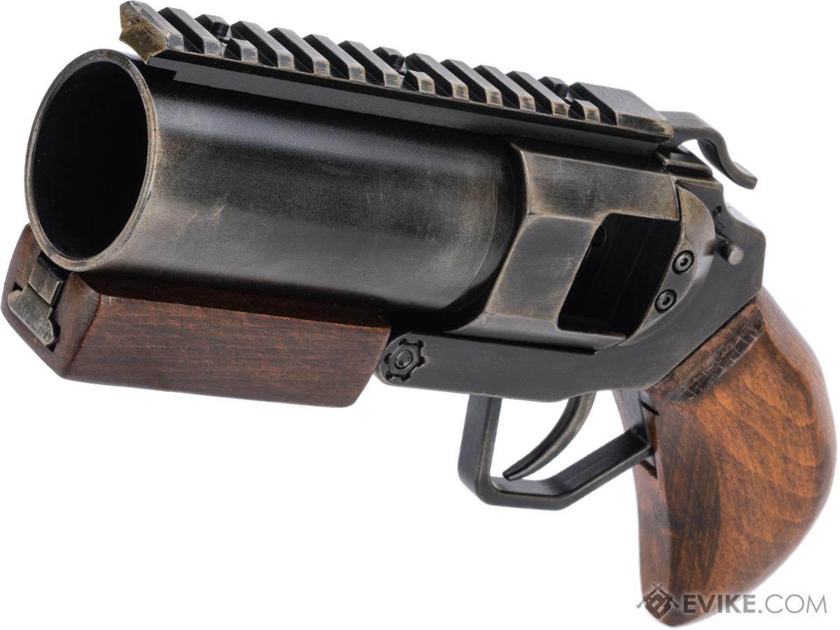
I used a flat bar so I used "L" brackets to hold the bar captive. Depending on the material used for the trigger bar/rod find a away to secure it to the control box. Picture #2: Cut the long end of the trigger rod/bar to match the lenght of the control box. shape and bend the tip so that sliding the trigger rod forward will depress the grenade valve. Transfer that measurement to one end of the trigger rod. Picture #1: Measure from the center of the XM PB4 grenade valve (the silver circle) to the top of the control box. I used a a 1/8 thick by 3/4 inch wide aluminum bar. Here is a video of the locking mechanism. I think the trouble is people are trying to make it more complex than it really is.
#40mm grenade launcher how to#
Edit: People still don't get how to make locking mechanism. put a layer of fiberglass, felt or duct tape to make sure the plastic does not come off or shift (see the green square in picture 2). Glue the strip of plastic to the side of the tube in such a way that when the launcher is extended the screw goes into the hole in the plastic. Drill a hole on one end for the screw in STEP 6 to go in to. Look around and use creativity and imagination. Look around your house/environment for a strip of plastic at least 1/8 of an inch thick and about 3 inches long. EDIT: Picture 2 & 3 - The Locking mechanism (13 seconds into the video) This is a strip of plastic glued to the side of the launcher.

Once the epoxy cures, paint your choice of colors. I epoxied it to the top and reenforced with more fiberglass and felt. I used sections of a 1 inch square pine dowel. an elegant weapon for a more civilized age.įigure a way to make some sort of control box on top of the outer tube. Attachments: sanding drum, cutoff wheel. (If you still buy the wrong part, I swear I will hunt you down and slap you!)įiberglass cloth tape 10"-12" wide by 2 yards.ġ/2"x 3/4" x 1/16" thick aluminum angle - "L". A total of 494 M75s had been built.2" schedule 40 PVC or ABS pipe 2ft or longer.įernco Proflex 2" CI, PL or ST to 1-1/2" Copper or 1-1/4"PL shielded coupler. This weapon, type classified as the M129, subsequently replaced the M75 in subsequent applications requiring a weapon of this type. Further development of the M75 ceased in 1967 as the XM129 reached maturity. Development of an improved derivative, the XM129, had begun in 1963 to rectify the problems. The weapon's mechanism allowed for it to "run away" under certain circumstances as well, functioning without any user input. A 1964 report on Army aircraft armament deemed the weapon inherently unsafe in its basic design, which allowed for live rounds to be left in the breech after firing had ceased. The weapon design reflected its fast development cycle. A gun pod for fixed wing aircraft, designated the XM13, was also developed. The M75 was also utilized in the early prototypes of the XM8 armament subsystem and in the prototype XM9 armament subsystem.
#40mm grenade launcher series#
The nose turret system, later type classified as the M5, was intended for the UH-1 series of helicopters, but was also used on the ACH-47A helicopter. This system was essentially identical to the XM138, but featured a revised ammunition feed. Tests were also conducted with the weapon mounted on a tripod for ground use.Ī redesign of the XM138 led to the XM5 armament subsystem by 1964. The resulting XM138, involving an turret fitted to the nose, was quickly integrated into the proposed organization for armed helicopter units. Philco-Ford was tasked with developing an armament subsystem utilizing the weapon for the US Army's new UH-1A helicopter. The weapon was quickly added to the arsenal of weapons being used in experiments with armed helicopters. The weapon was subsequently type classified as the M75. This new weapon, the first of its kind in the US Army, was subsequently designated as the XM75. In 1961, Philo-Ford filed the first patents for an automatic grenade launcher using the US Army's new high velocity 40mm ammunition. The weapon's barrel cycles back and forth as part of the firing process, with the rear battery position effectively locking the cartridge in during the fire phase of the operation cycle.

The large drum cam feeds linked ammunition into the weapon and also controls the rate of fire. The M75 grenade launcher is a 40x53mm, cam-operated, electric motor driven, air-cooled, grenade launcher that has a rate of fire of 215-230 rounds per minute.


 0 kommentar(er)
